|
How to Apply UltraCote
Surface Preparation:
The covering job can only be as good as the finish of the surface it's applied over. In order for the covering to properly adhere to a surface, the surface must first be smooth and clean. Sand the model using a sanding block and progressively finer sandpaper, with the final sanding being done with 320 grit paper. Vacuum away all of the dust, as specks of dust under the covering will leave unsightly bumps. Fill gaps and dents with a high-quality filler. If using light-colored UltraCote® (such as white or yellow), use a tan-colored filler that matches the wood color to prevent the filler from showing through.
|
 |
Pro Tip - Some professional builders "raise the grain" then sand a second time with 320 or 400 grit paper for the ultimate finish. After the model is sanded, use a damp cloth to wipe down the model. Some modelers prefer to use a fine-mist squirt bottle filled with water to dampen the surfaces to be covered. As the surface dries, imbedded wood fibers in the surface will "stand up." When dry, sand the surfaces again using 320 or 400 grit paper. Raising the grain now and sanding it off will prevent the grain from raising later under the covering, creating a bumpy finish. Vacuum the model thoroughly and avoid touching the model with oily hands. Your model is now ready for covering!
|
|
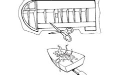
Trim Film to Size:
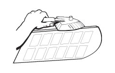
Start by covering the bottom of one wing half. Using scissors or sharp hobby knife, cut a piece of UltraCote® a few inches larger than needed to cover the wing. Remove the backing (save for later) and place the covering with the adhesive (dull) side down, centered over the wing. Set the covering iron to the application temperature of 220°F.
|
|
Pro Tip - If the iron you're using does not display the actual temperature, here is a tip that will ensure your iron is properly set. Water boils at 212°F. Allow your iron to warm up at a medium setting. When the iron reaches its stabilized temperature, carefully pour a few drops of water on the iron's surface. Adjust the temperature until the water just begins to boil off. This method is surprisingly accurate and is generally within 10°(of the exact application temperature of 220).
|
|
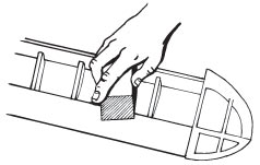
Tacking Covering to Spar:
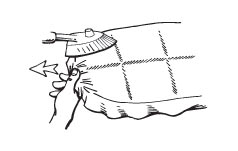
Tack the covering to the spar or the high point of the wing, using your iron as shown (an iron sock is highly recommended). Gently pull the covering toward the root and toward the tip, as you work the iron from the center of the spar to the root and tip of the wing. Press gently with the iron, allowing the heat (not pressure) to activate the adhesive and bond the covering to the high point. Ideally, the covering will naturally lay flat against the entire surface with a minimum of wrinkles.
|

|
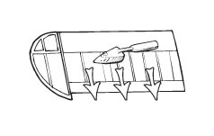
Covering a Solid-Sheeted Wing:
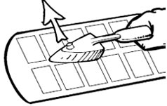
If covering a solid-sheeted wing, work from the center of the spar outward to the trailing edge and then to the leading edge as shown, using the iron at 220°F. If a wrinkle develops, the covering can be carefully lifted and reapplied.
|
|
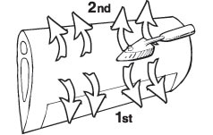
Covering an Open-Structure Wing:
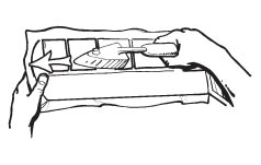
If covering an open-structure wing, work from the spar toward the trailing edge, gently sliding the iron (set at 220°) toward the trailing edge with the iron contacting two ribs. Using your iron, adhere the covering to the remaining ribs, working toward the tip and the root. Now complete the open structure leading edge, using the same method. If the leading edge is sheeted, then follow the technique listed above under "Covering a Solid-Sheeted Wing."
|
|
Sealing the Edges:
With the iron set to 220°F, seal the leading and trailing edges. Using a straight edge and a sharp #11 hobby knife, carefully trim the excess covering from the leading and trailing edge, allowing a minimum of a 1/4" overlap to wrap around the leading and trailing edge of the wing. Now seal the leading and trailing edges securely with the covering iron.
|
|
Wing Tip:
Depending on the amount of the curvature of the wing tip, high heat (up to 350°F) may be needed to shrink and stretch the covering to eliminate all the wrinkles. Preset the iron to 300°F. Pull and stretch the covering around the wing tip while applying heat with the iron. Remember, UltraCote® can be carefully lifted and repositioned to help eliminate wrinkles. This feature is beneficial, especially when covering sharply curved wing tips. Continue working, pulling, and heating the covering around the tip until the covering is past the center of the tip. It may be necessary to increase the temperature of the iron to achieve greater shrinkage to eliminate all wrinkles. Trim the excess covering using a #11 hobby knife, then reseal the covering on the wing tip.
|
|
Pro Tip - If sealing the covering in tight areas such as corners or fillets, using the Hanger 9 ProTrim Sealing Tool is very helpful and results in a professional finish.
|
|
Covering the Top of the Wing:
Using the backing from the wing panel that you just covered as a template, cut a piece of UltraCote® to be applied to the top of the wing. Be sure to cut a top panel, making sure that the adhesive is on the correct side. Apply the covering to the top of the wing using the same techniques as described in steps 3 through 6. Be sure that the covering overlaps a minimum of a 1/4" when trimming the edges and securely seal the edges with the iron.
|
|
Shrinking the Covering:
Now it's time to shrink the covering. With the iron set to 300°F, apply heat using the same pattern used to apply the covering starting at the spar and working outward. It may be necessary to increase the temperature to 320°F to get rid of stubborn wrinkles. Use the minimum amount of heat necessary to tighten the covering.
|
|
Pro Tip - Use heat, not pressure, to shrink the covering taught. If pressure is applied, gouges can be pressed into the wood. Let heat, not pressure, do the work.
Alternate Method: A heat gun can also be used to shrink the covering. This works particularly well over an open structure. It can also be used over a solid structure if a Hanger 9 Covering Glove™ is used to gently press the covering to the surface after heat is applied.
|
|
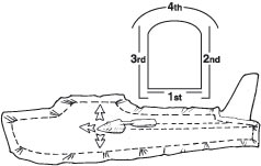
Covering Fuselages and Other Solid Surfaces:
The technique for covering fuselages and other simple flat surfaces is identical to covering a solid wing. Start with the bottom, then sides, and finally the top. First, tack the center of the surface down using an iron set to 220°F. Work outward from the center, bonding the covering to the surface. Trim and seal the edges. About 1/4" or more overlap is recommended when applying the next piece of covering. Shrink the covering, using the same method as described above.
|
|
Important: Even if you're experienced in applying other brands of covering, it’s important to read the following instructions. UltraCote® incorporates a unique multi temperature controlled adhesive and shrinkage system that makes achieving professional covering results easy.
|
|
Multi-Temperature Control System:
Understanding the benefits of this system and how to use it will make covering with UltraCote® easy and help to ensure professional results. When using UltraCote®, there are three important temperatures to be aware of.
|
Application Temperature-220°F (100°C):
At 220°, the adhesive on UltraCote® becomes active, allowing the covering to be attached to the model. While 220° will fully bond the covering to the model, it is well below the temperature that causes UltraCote® to shrink. This is exactly what's needed when first attaching covering to the model to prevent the covering from distorting.
|
Pro Tip -Many professional builders mark this temperature on their covering iron with a marker or striping tape for quick reference, as this temperature is used frequently whenever putting on covering.
|
Shrink On-Set Temperature-300°F (134°C)
At 300°F, UltraCote® begins to shrink. This is called the Shrink On-Set point. After the covering is attached using an iron set to 220°F, the next step is to shrink the covering. This initial shrinking is done with the iron set at 300°F.
|
Maximum Shrinkage Temperature-350°F (162°C)
At 350°F, UltraCote® reaches its maximum shrinking point. Raising the temperature above this point will not cause further shrinkage.
|
|


